
Variables To Consider
Laser variation
Despite lasers being specified as having a specific output power, the reality is that many lasers are not actually delivering the exact power advertised. This variation is not normally extreme, but some lasers vary as much as 5-10% from what their manufacturers describe. In most cases this is easily adjusted for by increasing or decreasing the power of the laser during the marking process. However, for our customers with lower power lasers, this can be a potential problem if their laser cannot deliver the minimum power needed to create a mark. For more information on required power for marking, please see our section on The process of establishing the correct laser settings to make TherMark laser marking materials successfully bond can be time consuming because of the number of variables involved. To expedite this process, it is possible to quickly determine the optimum settings using what is known as a “power grid”. In the laser bonding process, the two most important variables are the laser power and the speed with which the beam passes over the material.
A power grid is a graphic file constructed to apply different speeds and powers to different parts of the image; this allows the user to test multiple settings with a single pass of the laser, greatly reducing the time taken to find the best setting. In the picture below, each square in the grid has a different combination of power and speed settings as illustrated in the axes. The Y axis decreases power in increments of 10% from top to bottom (100% power at the top, 30% power at the bottom), while the X axis increases speed in increments of 10% from left to right (10% speed at the left, 100% speed at the right).
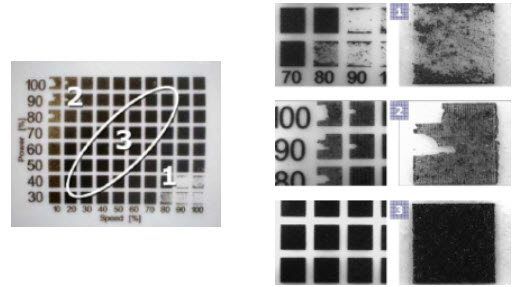
As you can see, optimal marking will only take place when the right amount of energy is transferred by the laser. Section (1) shows that when power is too low and speed is too high there is not enough energy to create a bond.
Likewise, section (2) shows that too much power at a low speed causes the material to be removed, possibly causing damage to the substrate surface.
The ideal “process window” lies in section (3) of the photo. Any of these settings will produce excellent marks on the substrate. Picking a setting in the middle will allow maximum latitude for variability between machines and material. In other cases such as a production environment, the fastest speed possible to create a mark may be preferred.
In summary, when using a TherMark product for the first time on a new substrate, it is advisable to run a power grid on a scrap part in order to determine the optimal settings for your laser/substrate/material/coating combination.
The laser beam
The laser beam in laser marking systems is focused through a lens which focuses the beam on to the surface to be marked. The focal spot size of the laser beam directly relates to the energy density of the beam: the tighter the focus, the higher the energy density and vice versa. Different lenses will focus the same beam differently resulting in a large variation of spot sizes from laser to laser, and thus of energy density, for the same output powers. Moreover, the laser beam quality (M2 value in technical terms) will strongly affect its focusing properties, the focal spot size, and consequently the energy density at the focus. Hence, proper adjustment of laser settings will be needed for successful marking.
Substrate variation
Variation in substrate composition is something to be aware of when marking metals with CerMark laser marking materials. If your parts to be marked do not have a consistent metallurgy or composition they may each react differently with our materials. When doing large production runs it is important to use parts that have the same composition in order to achieve consistent marks.
The optimum marking settings
The optimum marking settings will also depend on the thermal conductivity of the substrate being marked. The reason for this is that to successfully bond to the substrate the laser beam should heat the frit in the ink to certain high temperatures locally. When marking materials with high thermal conductivity, heat can dissipate due to thermal conduction. Therefore, higher settings may be required. With the same token, different materials have different heat capacities, which is the amount of energy required to increase the temperature by one degree. These two parameters combined will define the optimum settings required for each substrate. Usually metals require higher powers than plastics or glass materials.
Substrate thickness
Acrylic in various thicknesses.
ABS sheet (acrylonitrile butadiene styrene) ABS can be both laser marked and laser cut. The most common application is for laser marking however because the ABS is flammable when it is exposed to high sustained temperatures. We have cut up to 1/4" ABS with superior edge quality while thicker ABS can be cut but the edges may be either melted or discolored. Laser cut ABS leaves a slight odor on the cut area that dissipates after a few hour
Vinyl polymers
Can be both laser marked and laser cut. This is a case where the nose – knows. The laser will indeed cut and mark vinyl however the resulting out gas produced by the heated polymer is caustic and unless your shop is equipped to handle and scrub the ventilated fumes, laser cutting large amounts of vinyl is a hazard to the equipment (makes metal rust) and humans (not good to inhale). Vaporized vinyl has a sharp and pungent odor. In general we cannot recommend these materials for use in any laser system. Vinyl as in Polyvinyl chloride (PVC), polyvinyl fluoride (PVF) and polyvinyl acetate (PVAc) as the name implies when super heated by the laser to the point of vaporization has the potential to out gas chloride, fluoride and acetate fumes.
Paper, Card stock
Can be both laser marked and laser cut. These are good candidates for laser marking and cutting with the results depending somewhat on the properties of the dyes or inks used to determine the color of the paper. Proper ventilation is required. The material has a tendency to flame up if the laser beam is not moved rapidly through the mark or cut process.
Chipboard (ASTM D996)
Can be both laser marked and laser cut. The chipboard most are familiar with used in scrapbooking is a type of paperboard generally made from reclaimed paper stock (definition in ASTM D996); the term generally used in the US and is not to be confused with particle board which is glued wood chips. This is a good candidate for both laser marking and cutting depending again on the chemicals and bonding agents used in the creation process of the chipboard. Proper ventilation is required. The material has a tendency to flame up if the laser beam is not moved rapidly through the laser marking or cutting process
Aluminum (3mm)
Unfortunately this is not a good candidate for lower powered CO2 lasers (under 200 watts). The aluminum is reflective to the CO2 lasers fundamental wavelength and a relatively small amount of laser energy gets absorbed. To overcome this reflectance and absorption problem CO2 lasers in the multi kilowatt range are used with special gas assist techniques to enhance cutting and reduce the slag around the cut area.
Stainless (2mm)
This is a poor candidate for cutting with lower powered CO2 lasers (under 200 watts). Most laser companies recommend at a minimum of 400 watts with special cutting heads and gas assist for best cut results. While absorbing the CO2 lasers energy much better than aluminum, stainless steel is also reflective to the CO2 lasers fundamental wavelength and a relatively small amount of laser energy gets absorbed. High powered multi kilowatt CO2 lasers are used with special gas assist techniques to enhance cutting and reduce the slag around the cut area.
Plywood
Can be both laser marked and laser cut. 6mm is the maximum we would recommend with a laser under 100 watts. What we have found is the problem is more with the plywood glues (bonding agents) used. These adhesive bonds can behave like mirrors requiring variable amount of laser energy to get a good clean cut. Urea glue, adsorbs the laser radiation, and cut more easily. Phenol glue, commonly used in plywood for exterior use is more difficult to laser cut. Alder, Italian Poplar and Baltic Birch seems to work the best as it tends to be uniform in structure than ordinary plywood and remains fairly flat. Also air assist and good exhaust is mandatory to minimize burning. Failure to cut through in all areas is usually due to a change in composition in the material (voids, knots, percentage of glue, etc…).
Foam, various densities.
It really depends on the type of foam. Up to 25 mm on some foam such as polystyrene. Other foams such as polysulfone char and discolor and are not a laser friendly material.
Rubber, Epdm, Silicone Sheet.
Up To 25mm with varying results depending on the type of rubber or silicone. also air assist and good exhaust is recommended.friendly material.
Various other graphic and “scrapbooking” type materials.
Most non-metals. Such as marble, granites, tiles, cloths, fabrics, glass can be laser marked or cut.
Tip : When changing suppliers, make sure to test new parts and adjust your laser settings as appropriate.